
Silicon steel sheet manufacturer tells you how to find the grounding position of transformer iron chip
Iron chip grounding is a common type of fault in transformers. Once multiple grounding points are identified in the iron chip of a transformer, the specific location of the fault can be further investigated. After hanging the cover, grounding caused by debris is more intuitive and easier to handle.
But there are also certain situations where the problem cannot be found after a power outage, and in order to accurately locate the grounding address, the DC method can be used. Open the connection piece between the iron chip and the clamp, apply 6V DC to the silicon steel sheets on both sides of the iron yoke, and then use a DC voltmeter to measure the voltage between each level of silicon steel sheets in sequence. When the voltage is zero or the pointer indicates the opposite direction, it can be considered as the faulty grounding address.
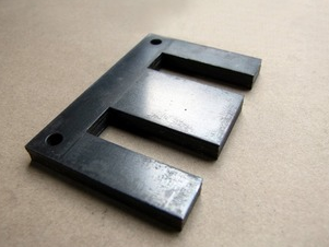
Alternatively, using the communication method, connect the low-voltage winding of the transformer to a communication voltage of 220-380V, where there is magnetic flux present in the iron chip. If there are multiple grounding faults, measuring with a milliampere meter will display the current. Measure point by point along the iron yoke with a milliampere meter. When the current in the milliampere meter is zero, it is the fault point. This current measurement method is more accurate and intuitive than the voltage measurement method.
If the above two methods still cannot identify the problem, the iron chip pressurization method can also be used. Disconnect the normal grounding point of the iron core and apply voltage to the iron chip using a communication test device. If the faulty point is not firmly connected, discharge sound will be heard during the boosting process, and the faulty point can be observed based on the discharge spark.
When the current of the experimental device increases, the voltage cannot rise and there is no discharge phenomenon, indicating that the grounding fault point is stable. At this moment, the current method can be used. Disconnect the normal grounding address of the iron chip and apply current to the iron core using a welding machine device. When the current gradually increases and the resistance of the faulty iron core is high, the temperature of the faulty point rises quickly, and the transformer oil will decompose and smoke, and then the location of the faulty point can be observed. Whether the problem can be eliminated can be verified by using the iron core pressurization method.
Article source: Silicon steel sheet manufacturerhttp://www.cheungshun.com
-
08-27
What is the function of the iron core of the silicon steel sheet in a transformer
The commonly used transformer iron core is generally made of silicon steel sheets. Silicon steel is a type of steel containing silicon, with a silicon content of. 0.8%~4.8%. The iron core of a transfo
-
08-27
The difference between hot-rolled and cold-rolled silicon steel sheets for transformers
In daily life, silicon steel sheets are widely used in motor cores. However, in terms of manufacturing silicon steel sheets, there are two aspects: hot rolling and cold rolling. Many friends do not kn
-
08-27
Is it better for silicon steel sheets to have a higher silicon content
The silicon steel sheet manufacturer's answer is not really satisfied with thinner silicon steel cores with higher silicon content. In terms of standards, the silicon content of thinner steel cores do
-
08-27
The difference between silicon steel sheet and silicon steel sheet
silicon steel sheetElectrical silicon steel sheets are commonly known as silicon steel sheets or silicon steel sheets. It is an electrical silicon steel with a silicon content of up to 0.8% -4.8%, mad
Copyright © 2026 Jiangmen Cheungshun Electric Products Factory Co., Ltd. All rights reserved xml site map